How Far Will My UHF RFID Tag Read? Link Budget Explained for India
Published 22 Oct 202611 min read

Short answer: A passive UHF tag reads as far as two things allow: the reader's field must reach the chip with enough power to wake it, and the chip's faint reply must get back to the reader. In India the first is capped by law at 2 W e.r.p. (35.15 dBm EIRP) in the 865–868 MHz band. With a −23 dBm chip on a dipole tag and a circular reader antenna at that limit, free-space theory gives about 20 m; plan a real installation at 40–50 % of that, roughly 8–10 m. Our read-range calculator runs the same sums with your own reader, antenna, cable and chip.
Datasheets quote read ranges and buyers compare them, but a range only holds for the reader, antenna, cable, tag and test conditions behind it. This guide explains the arithmetic, called a link budget, so you can work out what your own set-up should do, why a reader rated at 33 dBm may not use all of it with every antenna, and why a site reads shorter than the datasheet. Every figure below comes from a source listed at the end or is computed from those figures.
Two links decide the range
A passive UHF RFID tag has no battery. The reader antenna radiates power, the tag antenna collects a little of it, and once the chip receives more than its read sensitivity it wakes up and answers by changing how much of the signal it reflects (backscatter). So every read is two journeys:
- Forward link (reader to tag): does enough power reach the chip to wake it? This depends on the radiated power, the tag antenna and the chip's sensitivity.
- Return link (tag to reader): is the reflected reply still above the reader's receive sensitivity when it arrives? The reply weakens with the fourth power of distance, because it travels out and back.
The shorter of the two is the read range. The link-budget guide we used for the calculator says the forward link is almost always the bottleneck. The numbers show why: readers are typically rated to hear replies of −70 to −85 dBm, while the two chips in this article need −23 and −25.5 dBm just to wake up.
Step 1: radiated power and India's 2 W e.r.p. limit
Everything starts with what leaves the reader antenna. In decibels it is a sum: reader output power (dBm) minus cable and connector loss (dB) plus antenna gain (dBi). The result is the EIRP, the power an ideal isotropic antenna would have to radiate to produce the same field in the beam.
India's rules use a different reference. G.S.R. 853(E) of 10 December 2021 allows RFID interrogators in 865–868 MHz up to 2 W e.r.p. and defines e.r.p. relative to a half-wave dipole. A half-wave dipole has 2.15 dBi of gain, so e.r.p. is always 2.15 dB below EIRP: 2 W e.r.p. is 33.0 dBm e.r.p., or 35.15 dBm EIRP.
The same notification allows 2 W only within four channels of up to 200 kHz, centred at 865.7, 866.3, 866.9 and 867.5 MHz. Continuous transmission on a channel may not exceed 4 seconds, and an interrogator must leave at least 100 ms before transmitting on the same channel again. Rule 5 of the notification also requires the equipment to be type approved, so the reader model itself needs WPC Equipment Type Approval, which our WPC ETA and BIS checklist explains.
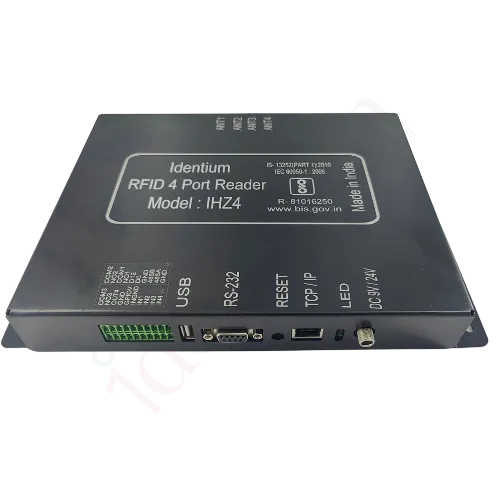
The power limit applies to the whole chain, not to the reader box. A reader rated "0–33 dBm" is legal or not depending on the antenna and cable behind it. Our IHZ4 4-port reader, for example, states 0–33 dBm, adjustable in 1 dB steps. With 3 m of LMR-195-class cable (about 1.09 dB of loss), the highest legal reader setting is:
| Antenna gain | Highest legal reader setting | Nearest 1 dB step |
|---|---|---|
| 6 dBi | 30.24 dBm | 30 dBm |
| 9 dBi | 27.24 dBm | 27 dBm |
| 12 dBi | 24.24 dBm | 24 dBm |
Put the other way round, a reader running at its full 33 dBm through that cable may feed an antenna of no more than about 3.2 dBi. Above that, the reader has to be turned down.
Step 2: the forward link, or waking the chip
Radio power spreads out as it travels. The loss between two antennas in free space, the free-space path loss, is 20·log10(4πr/λ) dB, where r is the distance and λ the wavelength. At 866.5 MHz, the middle of India's band, λ is 0.346 m, so:
| Distance | Free-space path loss at 866.5 MHz |
|---|---|
| 1 m | 31.2 dB |
| 2 m | 37.2 dB |
| 5 m | 45.2 dB |
| 10 m | 51.2 dB |
| 20 m | 57.2 dB |
Two rules of thumb follow. Path loss grows by about 6 dB each time the distance doubles, so every 6 dB lost from the budget halves the free-space range. And every 3 dB gained multiplies it by about 1.41; the guide puts it as roughly 41 % more theoretical range for each 3 dB of chip sensitivity.
The power available for the path is a plain sum: EIRP + tag antenna gain − polarisation loss − design margin − chip read sensitivity. Solve it for distance and you have the forward range. This is the Friis transmission equation written in decibels; the guide gives it as r = (λ/4π)·√(Ptx·Gtx·Gtag·τ/Pth), where Pth is the chip's wake-up threshold and τ describes how well the tag antenna is matched to the chip.
The chip
Read sensitivity is the weakest signal that wakes the chip, so a more negative figure is better. Two published examples: the UCODE 8 data sheet gives −23 dBm, and the M830 / M850 spec table gives −25.5 dBm. The 2.5 dB between them is worth about a third more free-space range. Our UHF labels and inlays and UHF tags name their chip on each product page, and the calculator lists more chips with their sources.
The tag antenna and polarisation
Chip sensitivities are quoted for a reference antenna; the UCODE 8 sheet states its tag sensitivity on a 2.15 dBi antenna, the gain of a half-wave dipole. A small tag, an on-metal tag or a band worn on the body has less effective gain, which is why a tag's own datasheet range is the real check. Polarisation adds a further loss: a circular reader antenna reads a linear tag dipole at any rotation but delivers about 3 dB less to it than a perfectly aligned linear antenna would, which matches the guide's 0–3 dB for polarisation mismatch.
Step 3: the return link, or hearing the reply
The tag answers by switching its antenna between two states, which changes how much power it reflects. What reaches the reader depends on the radiated power, the reader antenna gain (it transmits and receives through the same antenna), the tag antenna gain twice, the wavelength, and a factor called Δσ, the tag's differential radar cross-section, which the guide puts at 0.005–0.02 m² for commercial inlays. Because the signal covers the distance twice, it falls with the fourth power of distance: double the range and the reply arrives 12 dB weaker.
Two of those inputs are rarely on a datasheet: the reader's receive sensitivity and the tag's Δσ. So treat the return-link figure as a cross-check. Where it comes out shorter than the forward link, enter your reader's stated receive sensitivity before you trust it.
Worked example: a 9 dBi antenna at a dock door
- Radiated power. A reader at 30 dBm feeds a 9 dBi circular antenna through 3 m of LMR-195-class cable (1.09 dB). EIRP is 30 − 1.09 + 9 = 37.91 dBm, which is 35.76 dBm e.r.p. That is 2.76 dB over India's 33 dBm e.r.p. limit, so the reader must come down to 27.24 dBm or less: 27 dBm on a reader with 1 dB steps.
- Forward budget at the limit. 35.15 dBm EIRP + 2.15 dBi (a dipole tag) − 3 dB (circular antenna, linear tag) − (−23 dBm) (a UCODE 8 chip) = 57.3 dB available for path loss.
- Free-space range. The path loss at 1 m is 31.2 dB, which leaves 26.1 dB. 1026.1/20 is about 20.2, so the theoretical free-space range is about 20 m.
- Design margin. Take 6 dB off for orientation, reflections and materials and the range halves to about 10.1 m.
- Return-link check. With a reader that hears −85 dBm and a tag Δσ of 0.01 m², the reply meets the reader's sensitivity at about 8.9 m with the same margin. On these assumptions the reply, not the wake-up, sets the limit, which is exactly the case where your reader's stated sensitivity is worth looking up.
- Planning figure. The guide's planning baseline of 40–50 % of the theoretical figure gives 8.1–10.1 m, in line with the margin and return-link results. For a committed service level the guide suggests 30 %, about 6 m.
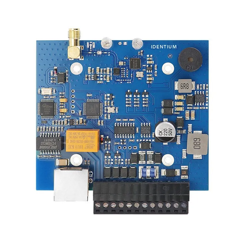
Swap the chip for an M830 / M850 at −25.5 dBm and the free-space figure grows to about 26.9 m. Swap the reader for one that tops out at 26 dBm, such as our IDTS-RM26 reader module (0–26 dBm), and the same antenna and cable radiate 33.91 dBm EIRP, 1.24 dB under the limit: the UCODE 8 figure drops to about 17.5 m. Below the cap, the reader's own maximum is what limits you.
What a higher-gain antenna buys under a power cap
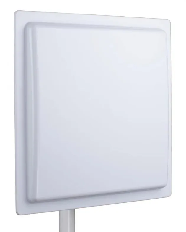
Antenna gain does not create power; it concentrates it into a beam. Once a set-up is at 2 W e.r.p., moving from a 9 dBi to a 12 dBi antenna means turning the reader down by the same 3 dB, so the forward range along the beam stays where it was. What changes is the shape: the 12 dBi beam is narrower and suits a lane or a long aisle, while a 6 dBi antenna covers a wide, short zone such as a counter. Our antenna guide covers beamwidths and read-zone design.
Gain does help the return link, because the reader also receives through its antenna. In the worked example, the 12 dBi antenna lifts the return-link estimate from about 8.9 m to about 10.6 m, so the forward link (10.1 m with the margin) becomes the limit again. And below the cap, every extra dBi adds forward range directly.
Cable loss is paid twice
Every metre of coax between reader and antenna costs power on the way out and again on the tag's reply. Attenuation at 900 MHz from a coax selection guide, converted from dB per 100 ft:
| Cable class | dB per 100 ft | dB per m | 3 m run | 10 m run |
|---|---|---|---|---|
| LMR-400 | 3.9 | 0.128 | 0.38 dB | 1.28 dB |
| LMR-240 | 7.6 | 0.249 | 0.75 dB | 2.49 dB |
| LMR-195 | 11.1 | 0.364 | 1.09 dB | 3.64 dB |
| RG-58 | 16.5 | 0.541 | 1.62 dB | 5.41 dB |
RG-58 varies with its construction, so check the figure for the cable you actually buy; connectors and adapters add a little more. On the forward link, a reader with headroom can win the loss back by raising its power, because the legal cap applies at the antenna. The return link cannot. In the worked example, 10 m of RG-58-class cable instead of 10 m of LMR-400 costs about 4.1 dB on the reply and shrinks the return-link estimate from about 8.8 m to about 6.9 m. Keep runs short, mount the reader near the antenna, and use low-loss cable for long runs.
From theory to site: why real range is shorter
Datasheet ranges assume free space, a single tag, perfect broadside orientation and zero cable loss, and the guide adds that the tag tested may be the best sample of its production batch. On a real site it lists these typical extra losses:
| Effect | Typical extra loss |
|---|---|
| Polarisation mismatch | 0–3 dB |
| Tag orientation (tumble) | 3–6 dB |
| Multipath and reflections | 2–6 dB |
| Material absorption | 1–4 dB |
| Cable and connectors | 1–3 dB |
| Several tags in the field | 1–3 dB |
| Regulatory headroom | 0–1 dB |
| Cumulative | 8–20 dB |
A 12 dB derating cuts range by about three quarters, which is why the planning baseline is 40–50 % of the theoretical figure. After the sums, test on site with the real items: metal and liquids behind a tag change more than any table can. Our guides to on-metal tags and tags that do not read cover the usual fixes.
Using the calculator
- Reader. Pick a reader whose spec states a transmit power, or type the output power. Readers whose spec gives no dBm figure are left out rather than guessed.
- Antenna and cable. Pick an antenna with a stated gain, then the cable type and length; the loss fills in. Antennas specified only for the 902–928 MHz export band sit in their own group and switch the calculator to 915 MHz with the India check turned off.
- Tag. Pick a chip with a published read sensitivity, or type one from the chip's data sheet.
- Read the results. The page shows the EIRP and e.r.p., whether the set-up is within 2 W e.r.p. and the highest legal reader setting, then the theoretical range, the range with your margin, the return-link limit and the planning band. Copy the link to share the exact settings.
Open the UHF RFID read-range calculator: it opens on the defaults used in this article, flags the 2.76 dB excess, and its "Set the reader to the legal maximum" button reproduces the worked example.
Parts used in the example
- IHZ4 4-port fixed reader, 0–33 dBm in 1 dB steps: ₹55,000 + GST. All multi-port models are under UHF RFID multi-port readers.
- 9 dBi circular antenna, 865–868 MHz, N-female: ₹8,000 + GST.
- 12 dBi circular antenna for long, narrow zones: ₹11,000 + GST.
- 8 dBi directional PCB antenna IDTS-RA8190, 865–868 MHz, SMA-female: ₹13,500 + GST.
- Every antenna with its gain, polarisation and band: RFID antennas. Readers with the antenna built in have no cable to budget: integrated readers.
Related guides
Sources
- G.S.R. 853(E), 10 December 2021: Use of Low Power Equipment in the Frequency Band 865–868 MHz for Short Range Devices (Exemption from Licence) Rules, 2021 (e.r.p. definition; Table IV: 2 W e.r.p., four channels, 4 s / 100 ms; rule 5: equipment type approval), accessed 22 October 2026
- How to calculate UHF RFID read range: forward and return link formulas, loss table and planning fraction, accessed 22 October 2026
- UCODE 8/8m product data sheet SL3S1205_15, Rev. 3.6, 2 December 2021 (read sensitivity −23 dBm, 2.15 dBi antenna), accessed 22 October 2026
- M800 series spec table (M830 / M850 read sensitivity −25.5 dBm), accessed 22 October 2026
- Coax selection guide: attenuation per 100 ft at 900 MHz for LMR-400, LMR-240, LMR-195 and RG-58, accessed 22 October 2026
Frequently asked questions
How far can a passive UHF RFID tag be read in India?
Is 33 dBm legal for a UHF RFID reader in India?
What is the difference between EIRP and e.r.p.?
Does a higher-gain antenna increase read range?
How much range does cable loss cost?
Why does my tag read shorter than its datasheet range?
UHF RFIDRead RangeLink BudgetRFID AntennaIndia 865–868 MHz
Keep reading
More guides

More in Technology explained
- Will RFID Tags Made in India Work in Europe, the UK, the Gulf or Africa? The ETSI 865-868 MHz Compatibility Guide
- GS1 and EPC Encoding for Indian Retail Suppliers: SGTIN-96 Explained
- RFID Data Security in India (2026): Is RFID Safe? Cloning, Skimming & Encryption Explained
- RFID vs QR Code in India (2026): Cost, Speed, Durability & Which Wins
- NFC vs RFID — What's the Difference? India Guide 2026